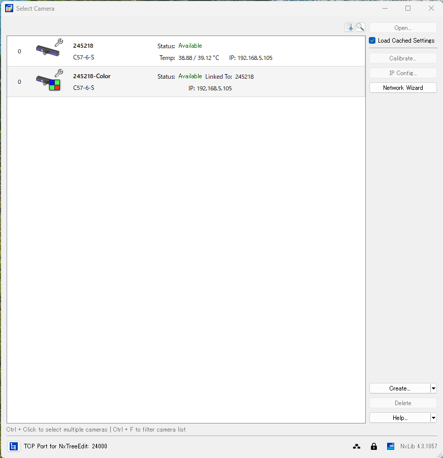
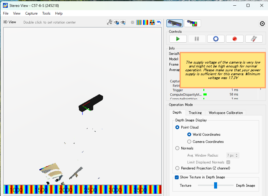
I have connected a C57 camera to a PC and am using an OMRON S8VK-S24024 (24V, 10A, 240W) as the power supply.
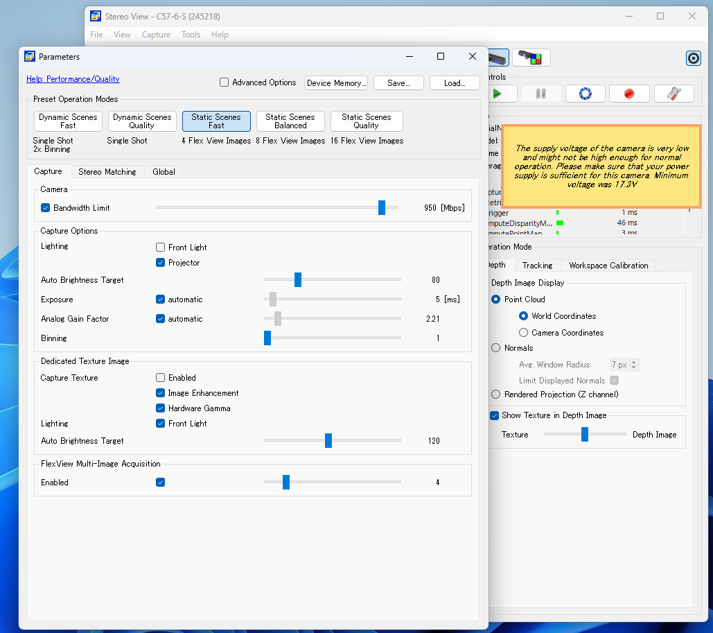
I selected this power supply because the manual specifies 24V and 10A. However, after launching NxView and opening the camera, a low-voltage warning appears on the imaging screen, as shown in the attachment. Note that the front light is turned off, and nothing other than the camera is connected to the power supply.
Please advise on the following points:
Q1. I selected the power supply in accordance with the manual; is the power supply currently insufficient?
(Did I make a mistake in selecting the power supply?)
Q2. Should I prepare a power supply with a higher wattage?
If so, how should I determine the appropriate wattage?
Could you please provide guidance on this?
I have attached screenshots of NxView (taken before opening the camera and when the low-voltage warning appears) as well as the parameter screen and parameter settings.
As you pointed out, I am currently using “AWG 18(0.75 sq) 5m Cable” connected to “Optonic Part Number: 13057(Cross sectional area per wire (metric): 0.5 mm2)”.
If it is not possible to shorten the length, I understand from the “long-cable-lengths” section of the manual you provided that it is best to connect “AWG 18(0.75 sq) 5m Cable” using “Adapter Cable: M12 5-Pin - M8 4-Pin Optonic Part Number: 11078” and “M12 5-Pin Cable (Open Endings) Optonic Part Number: 11144 (5 m)”; is that correct?
Also, given the current parameters, what is the current value used for the cable voltage drop calculation? (Since the front light is off, I assume it is not 10A.)
5m cable with 0.75mm² (voltage drop 2.2V) and another
5m cable with 0.5mm² - Optonic Part Number: 13057 (voltage drop 3.3V)
leads to a total theoretical voltage drop of 5.5V, which brings you down to 18.5 V and thus below the required minimum of 20V. Note that there is still a gap of 1.2V from the theoretical 18.5V to the 17.3V shown by NxView in your screenshot.
With the camera open, you can have a look at the minimum voltage node to see the current supply voltage. Please check if this voltage is close to the expected 24V.
When switching to adapter 11078 (0.3m cable length with a cross sectional area of 0.34mm²), the expected voltage drop on the adapter should be around 0.3V. In order to match the complete length of 10m, the remaining cable then must be 9.7m long. With the 0.75mm² cable, this would result in a voltage drop of about 4.6V and still bring you below the required 20V. This is why the manual recommends 27V power supply for 10m with M8 connector in the long-cable-lengths guide. Alternatively, you can continue with 1.5mm² on the M12 side of the adapter, which would result in a voltage drop of 2.4V. Combined with the 0.3V across the adapter, this would keep you above the 20V.
Your options summarized:
Input 27V, 11078 (0.3m), 5m 0.75mm² → voltage drop 4.9V, supply min. 22.1V
Input 24V, 11078 (0.3m), 5m 1.5mm² → voltage drop 2.7V, supply min. 21.3V
All the calculations assumed the maximum current of 10A.
Thank you for your reply. Upon checking /Cameras/245218/Status/MinimumVoltage, I found that it was 23.853616714477539062 at the time of connection, but it changed to 17.748226165771484375 as imaging continued.
I plan to try changing the cable. What kind of imaging issues would occur in this state? Would the projector LED stop emitting light, or would the system fail to capture an image?
Also, just to confirm: the “Trigger In” signal on the M8 connector does not need to use a 1.5 mm² wire, correct? (Is 0.5 mm² acceptable?)
DC voltage drops below 20 V might result in reduced LED output power and the device could also intermittently switch to draw power from PoE if available.
Regarding your question:
Also, just to confirm: the “Trigger In” signal on the M8 connector does not need to use a 1.5 mm² wire, correct? (Is 0.5 mm² acceptable?)
Yes, that is acceptable. “Trigger” and “Flash” are signal lines and thus carry only very low currents, so the cross sectional area is not critical. The GPIO Port for the C-Series says max. 30mA for the output (“Flash”). For the input (“Trigger”) it is even less. As a rough estimate, the voltage drops across a 10m cable are 10mV for 0.5mm² and 22mV for 0.25mm².
I would like to clarify one point regarding the answer I received.
I previously considered using PoE, but since a supply of 24V/10A or higher is required, I am currently powering the unit via a switching power supply.
This leads to a question: If I were to use PoE in conjunction with the current setup, could it compensate for any voltage drop from the switching power supply? My assumption is that a switchover would simply occur; since PoE cannot supply 10A, the voltage drop would likely still happen regardless.
If I were to use PoE in conjunction with the current setup, could it compensate for any voltage drop from the switching power supply?
The camera can only use either DC or PoE, not both in parallel.
I previously considered using PoE, but since a supply of 24V/10A or higher is required, I am currently powering the unit via a switching power supply.
Can you tell us what the minimum possible cable length and the required flash duration and brightness is? Those requirements would be immensely helpful for us while assisting you to dimension the power supply of that setup.
Thank you for your reply.
Please give me a moment to measure the minimum cable length on-site.
Regarding the “required flash duration and brightness,” I have been setting these based on intuition. What should I actually use as the basis for these settings?
For reference, the current settings are as follows (in JSON format):