We occasionally receive questions from customers regarding the difference between the Operating Distance specification and the starting value in the data table.
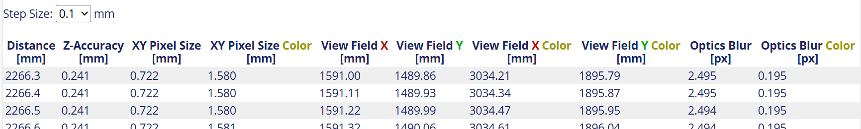
For the C57-8-L, the specified operating distance is 2200 mm and above, but in the data table, the distance for workload starts from 2264 mm (when Step Size is 0.1 mm).
Is there any reason for this difference?
For the C57-8-L, would it be possible to provide a data table starting from 2200 mm?
2264mm is the exact start of the operating distance for this model, so there is no data for smaller values.
The operating distance summary shows a rounded value. It always rounds down the minimum distance to avoid degenerate cases where the operating range becomes empty. Unfortunately this causes quite a large discrepancy in this case due to the big step size of 100mm for this model with a large volume. We will look into a better way to display this in the future.
2264mm is the exact start of the operating distance for this model, so there is no data for smaller values.
The specification states that the operating distance for this model starts at 2200mm.
So, do you mean the correct minimum operating distance is 2264mm, not 2200mm?
Does this mean the specification is incorrect?
Yes, the entry you mean is rounded and not the exact operating distance. The exact range is the one listed in the table.
You should generally not rely on the specification of the operating range to this precision, though. It is a theoretical value and can vary a bit in the actual camera. The operating range is computed based on an estimation of the blur, which can vary depending on the lens and how exactly it got focused during manufacturing.
Just to summarize, these are the points we often get questions about (please correct me if any of the answers are wrong):
The difference between the Operating Distance shown in the spec sheet and the starting distance in the data table
(Answer: The data table values are correct. However, please allow some margin as this can vary depending on the environment.)
Accuracy of the measured volume
(Answer: It includes about a 5% margin, but please allow some margin in your considerations.)
Whether the accuracy listed in the table is based on actual measurements or theoretical values
(Answer: These are theoretical values. Actual results will vary depending on the environment and the target object and will generally be worse than the theoretical values.)
It would be a big help for both us and our customers if this explanation could be added to the website or the manual.
as Daniel is on holiday for a few days I jump in here, and I agree with your summary.
Regarding the accuracy: this is the 1-sigma noise level which can be expected with FlexView 16 on a white, matte surface. We verified this on some configurations. If the surface is more difficult (dark, reflective, etc.) or the customer is using less images, this value will be worse.
Thank you for providing the additional information.
It would be helpful if this information could also be included in the manual or on the website.
Additionally, we recently had a support case where a customer encountered an error when implementing the workspace calibration code for Ensenso-XR by referring to the sample code in the manual.
Then I shared the following XR-specific information with the customer, and the issue was resolved: Operation of XR-Series Cameras – Image Acquisition
It would be helpful to add a note or a link for Ensenso XR users on the following page, as the customer referred to this sample code: Workspace Calibration – Code Examples
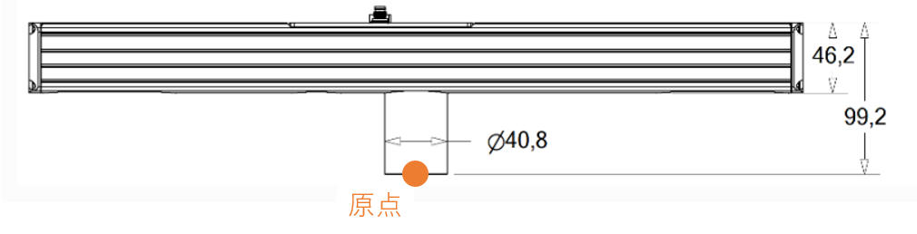
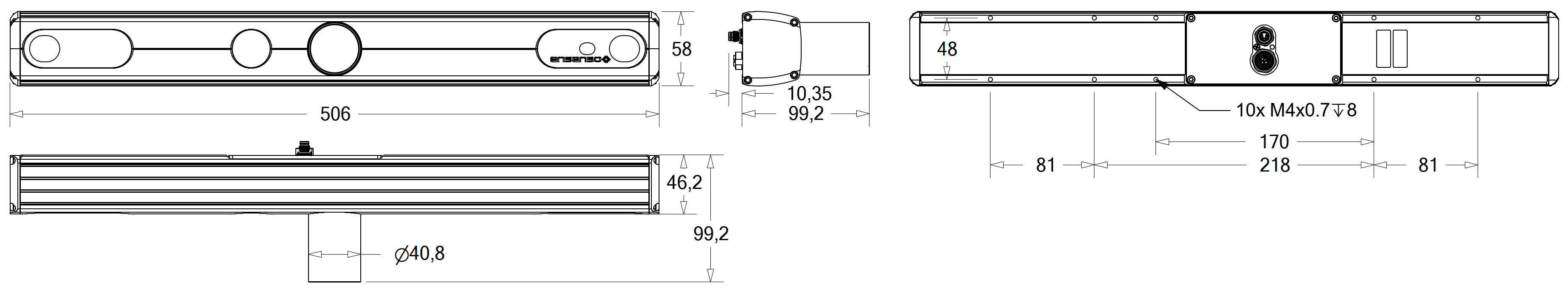
I understand that the origin of the working volume is at the center of the front of the projector lens tube (the orange dot in the diagram). Is that correct?
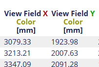
Where is the origin of the View Field Color? Is it the same point, or is it located where the color camera is mounted? If it is at the color camera position, could you please specify its exact location?
For the real, calibrated camera the origin will be at the calibrated projection center of the left lens and the color lens respectively. This position is not calibrated to the housing and has to be corrected using a workspace or hand-eye calibration.
For planning you can assume that the origin is roughly in the center of the camera behind the respective lens on the left side of the camera. Unfortunately the CAD models on our website don’t use this origin, but we are working on creating CAD models that include the working volume and will make this clear.
I would like to clarify my question.
I understand that the origin when workspace calibration is not performed is near the left camera.
My question this time is about the origin of the working volume listed in the spec spreadsheet.
I think the origin of the stereo camera’s working volume is the center of the projector, and the origin of the color camera’s field of view is the position of the color camera. Is that correct?
the stereo measurement volume is symmetric around the camera center, yes. The color sensor covers at least the stereo volume, and is also tilted with the same vergence as the left sensor. I’m not sure about the reported sizes though, we would need to check that in detail in the code.
My question this time is about the origin of the working volume listed in the spec spreadsheet.
I think the origin of the stereo camera’s working volume is the center of the projector
Ah yes, the view field reported by the selector is centered on the camera. It does not start at the front of the projector lens (the orange point in your drawing) though, but depth 0 still starts from the stereo lenses. So it is more in the center of the housing rather than at the front of the projector lens tube.
The color sensor covers at least the stereo volume, and is also tilted with the same vergence as the left sensor. I’m not sure about the reported sizes though, we would need to check that in detail in the code.
I checked and the reported color sensor view field is relative to the color sensor at the moment. It does not take into account the rotation of the color sensor. It would probably be better to compute the distance the same as for the stereo view field.
Unfortunately the CAD models on our website don’t use this origin, but we are working on creating CAD models that include the working volume and will make this clear.
is there an estimated time of release for these CAD-models including the camera’s working volume?
you can already export them from NxView (File → Save → Camera Model) or using the SaveCameraModel command. At the moment, the command can only create PLY meshes, though.
A STL STEP export will come later. I can’t promise any date for it, but it will take at least a few months.