I was creating a C++ program using one C57 camera and a hardware trigger,
but I now need to image a specific part of the workpiece with another C57 camera to obtain a more accurate shape.
And I want to use the same sensor to trigger both C57 cameras.
(I want both cameras to image simultaneously as much as possible.)
Therefore, I have the following questions:
Q1. Do I need to actually wire the sensor to the additional C57 camera?
Or can I use a software method to use the hardware trigger wired to one camera on the other?
(If wiring to both cameras is necessary, could you please provide an example of the wiring?)
Q2. Are there any sample programs that show how to open multiple cameras?
Q1. Do I need to actually wire the sensor to the additional C57 camera?
if you want to use a hardware trigger you need the wires.
If you only want to synchronize the two cameras together but can trigger from software, there is an easier solution using PTP synchronization. See this guide for more information.
(If wiring to both cameras is necessary, could you please provide an example of the wiring?)
The following was written in the Hardware Trigger chapter of this guide:
The output of camera “1234” is electrically connected to the input of camera “2345”.
Based on the above, I would guess that the connection method should be as follows, but what do you think?
 the input of camera "1234" is electrically connected to the trigger sensor, and the output of camera "1234" is electrically connected to the input of camera "2345".
I want to run camera “1234” in hardware trigger mode, and “2345” should run hardware synchronized to the hardware triggered images of “1234”.
Or
would it be better to connect the output of the same sensor to the input signal of each camera?
Q1-2.
Q1-2-1. Is the input signal for the C57 camera a sync input or a source input?
Q1-2-2. Also, is the output signal a sync output or a source output?
Q1-2-3. When the sensor is ON, what is the total current flowing to the inputs of the two cameras? I want to check if it exceeds the sensor’s maximum switching capacity (rated current).
Q1-2-4. Also, when the sensor is OFF, I want to check if the small leakage current flowing through the sensor prevents the camera input from resetting (turning OFF).
Q1-2-5. If possible, could you please illustrate an example of the wiring with a DC24V PNP sensor?
You can do either: connect the trigger signal to each of the cameras separately or chain the cameras together. The first one is probably easier. For the latter, you have to enable the output of the first camera and the trigger signals might accumulate some latency over the chain.
I will answer your questions regarding the electrical specifications.
For Q1-2-1 and Q1-2-2 I am assuming you are referring a “sink input/output” when you did write “sync input/output” and I will answer based on this assumption. Please correct me if I am wrong.
Q1-2-1. Is the input signal for the C57 camera a sync input or a source input?
The input signal for the C57 is a sink input. Current is flowing in the C57.
Q1-2-2. Also, is the output signal a sync output or a source output?
The output signal coming from the C57 is a source output. Current is flowing out of the C57.
Q1-2-3. When the sensor is ON, what is the total current flowing to the inputs of the two cameras? I want to check if it exceeds the sensor’s maximum switching capacity (rated current).
If a high signal is present at the input, the total current flowing into a single camera is around 2mA, 3mA at max. For two cameras the total input current is around 4mA, 6mA at max.
Q1-2-4. Also, when the sensor is OFF, I want to check if the small leakage current flowing through the sensor prevents the camera input from resetting (turning OFF).
I do not really understand the question here. Can you please give more details? What do you mean when you write “prevents the camera input from resetting (turning OFF)”?
Q1-2-5. If possible, could you please illustrate an example of the wiring with a DC24V PNP sensor?
I am assuming you are referring to a standard PNP sensor that outputs 24VDC if triggered and is high-z if not triggered. You can connect the output of such sensor directly to the trigger input of the C57. Sensor and camera need to share the same GND, but no additional circuitry should be required. If you are planing to use some non-standard PNP sensor, we need more details about the sensor.
I asked the question to confirm whether the input would remain constantly on due to the sensor’s leakage current and the camera’s input impedance.
Since the input is a sink input and it is internally pulled low, the input should be low as soon as the sensor stops driving it high.
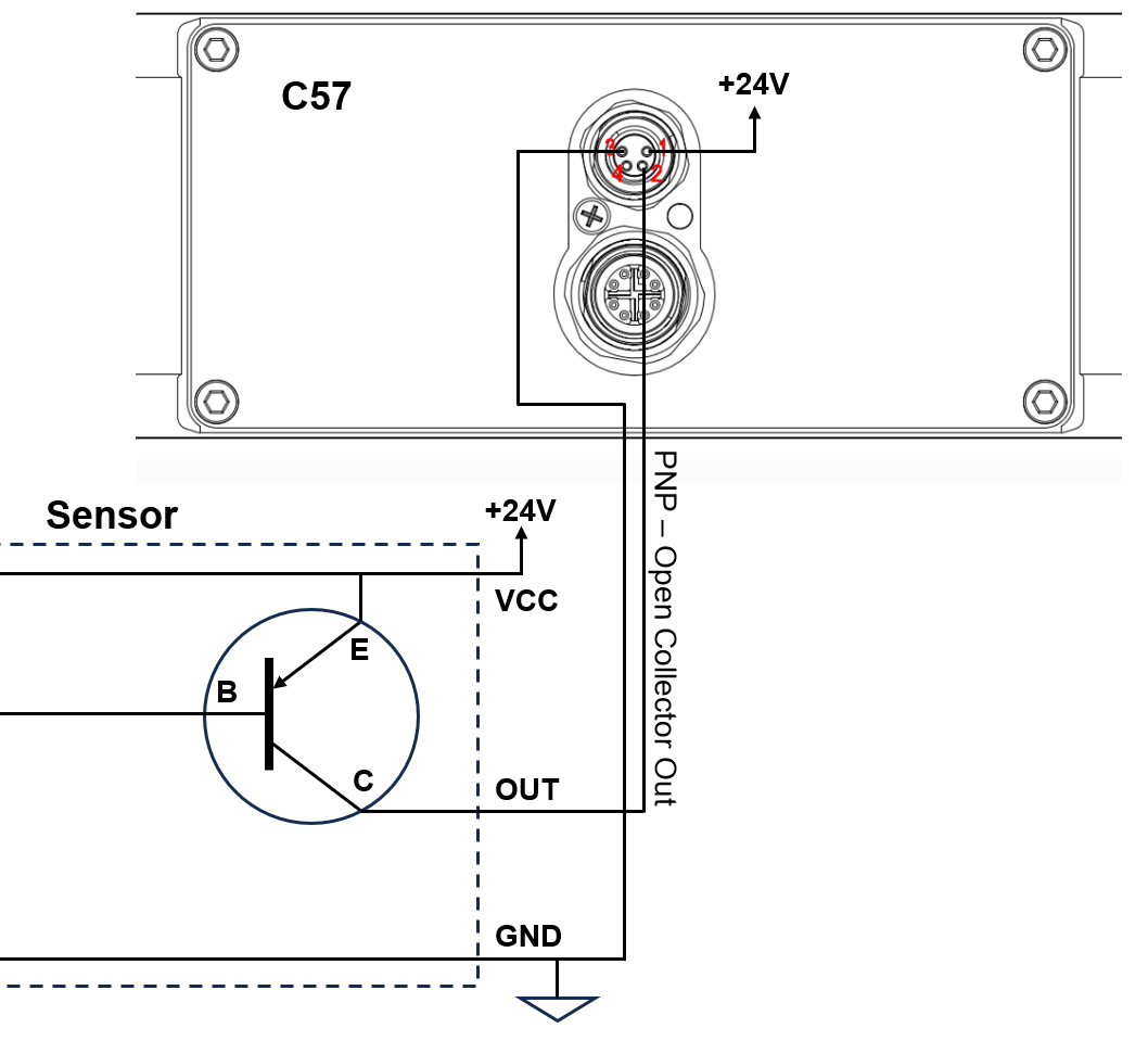
Unfortunately, I cannot access the datasheet of the PR-G51CP sensor. I guess it has a standard PNP Open Collector output. A general wiring example could look something like this:
Using a timer should also be possible to trigger the C57. I am not familiar with the H3CR-AP but from looking at the datasheet I think the following connections should be possible: Connect the C57 trigger input (2) to pin 1/11 of the timer. Then connect 24VDC to pin 3/9 of the timer and GND to pin 4/8, or vice-versa depending on your desired trigger condition.
Please let us know if you have any further questions.
I also understand that the logic remains stable even when the input signal is open
because it’s internally pulled down.
(I was thinking of adding a resistor between the signal and ground just in case.I’m glad that no extra circuitry was added.)